
Built for the 1862 Exhibition at South Kensington
I first saw this engine about 4 years ago in the Science Museum in South Kensington. I was immediately impressed by its sheer elegance and, to me, beauty, that there and then thought I must make one! Unfortunately its situation in the museum, in a glass case was not really conducive to photography and meant I couldn't make as detailed an examination as I would have liked, parts were tantalizingly un-viewable.
Contact was made with the engine curator who promised me access to it when they were removing it to install an electric motor drive. In spite of repeated reminders and assurances the promise was not fulfilled and I had to make do with some fairly bad photographs and a lot of inspired guesswork.
I was very fortunate to be able to interest Anthony Mount, that great authority on historic engines, in the project, he too wanted to build it and in due course, from the scant information available, produced a set of working drawings, he also made the patterns for the castings involved and arranged for their productions at his chosen foundry.
The building commenced in May and took 6 months of continuous effort. I've no idea how many hours were involved but I didn't manage to get a summer holiday. It was not without problems, but consultation with Anthony in most cases produced an immediate solution although I must admit some took a touch longer!
Anyway I am well satisfied with the result it has been run on air and works well at about 10-15 psi. I am indebted to Anthony Mount for his encouragement and undoubted ability.
I hope you like it!
Rusty Titford
Footnote
I understand that Anthony will shortly be writing a series of articles covering its construction, which will in due course be published in the engineering press
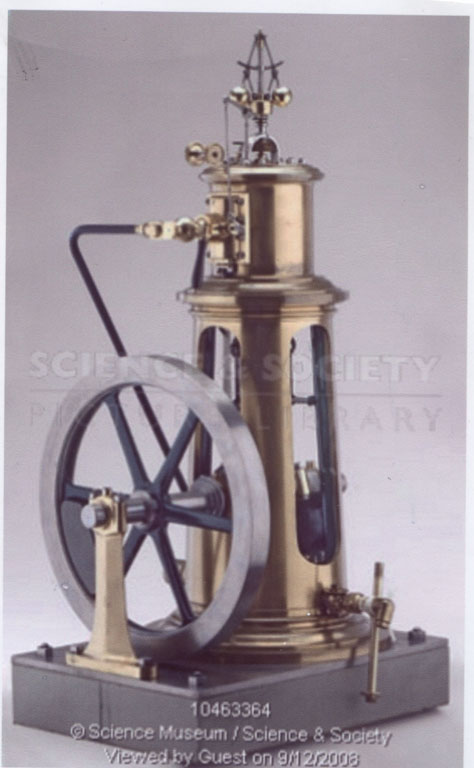 |
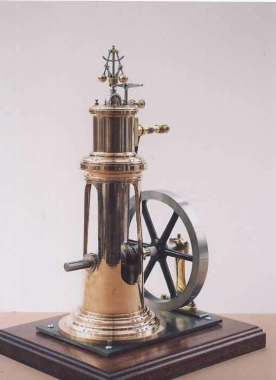
The ''official '' photo from the Science Museum Website |
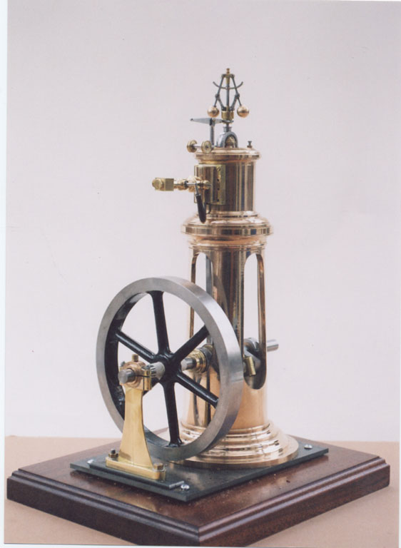 |
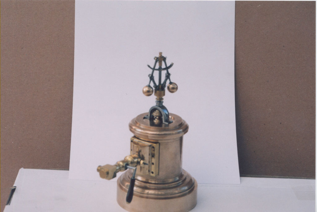
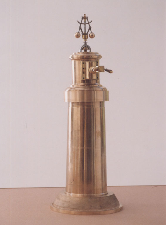
The Same view of my nearly completed engine |
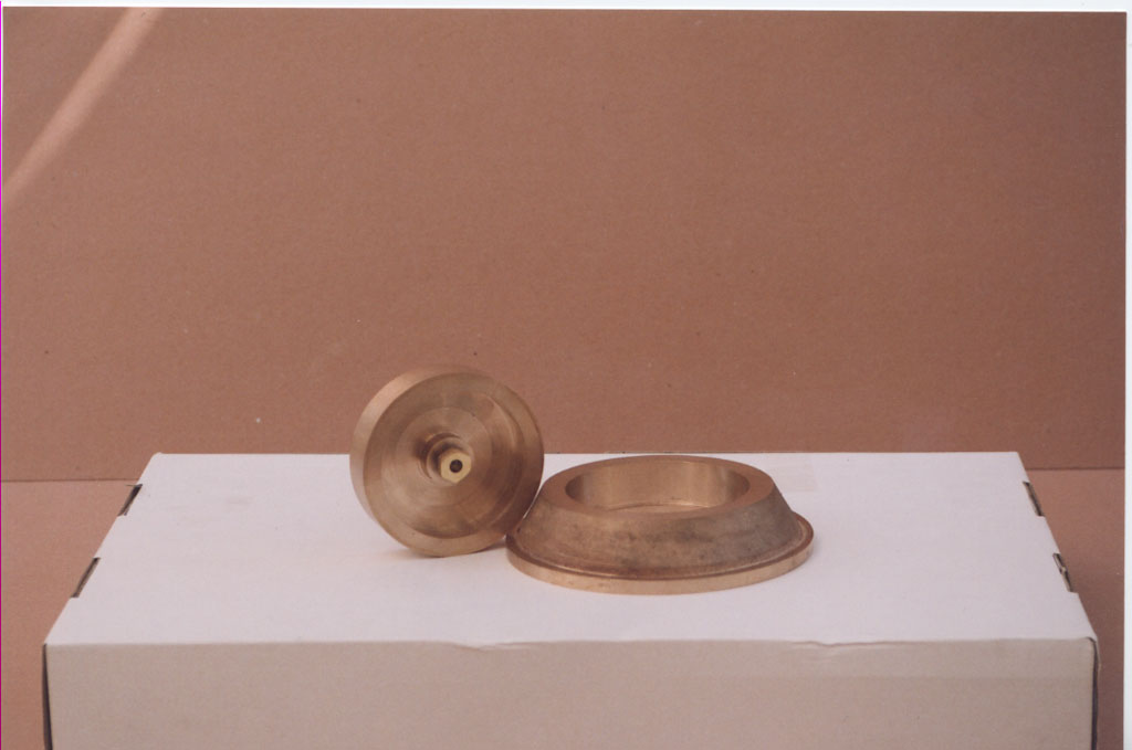 |
The cleaned up castings of the cylinder base and column base |
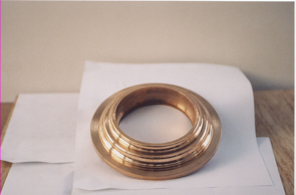 |
Column base with mouldings worked using home produced form tools of hardened and tempered gauge plate |
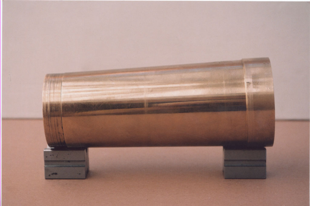 |
Outside of column turned the ''relatively'' easy bit!! Ofset 2 degrees. Worked between centres with end plates fitted. |
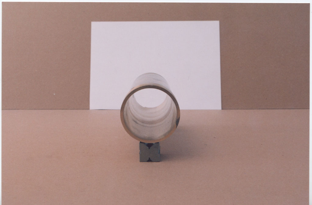 |
Inside of cylinder the hard (nearly impossible) bit. Turned on a WARCO 1347 with 2" topslide movement! |
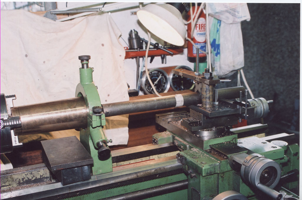 |
A stout (2.5") boring bar was needed and a special 'tool post' made to take the stresses involved. |
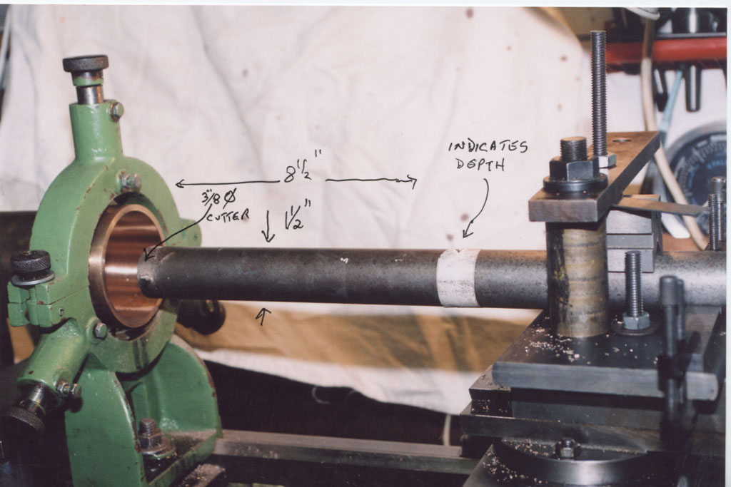 |
This had to be worked in 4 x 2" moves but how to tell when this tool is touching the job? You can't see down the column. (Did it by sound!) |
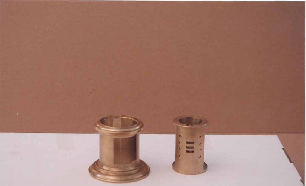 |
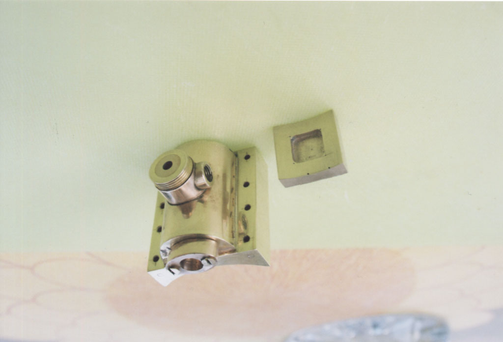
Cylinder casing + cylinder. Note curved surface of ports. |
 |
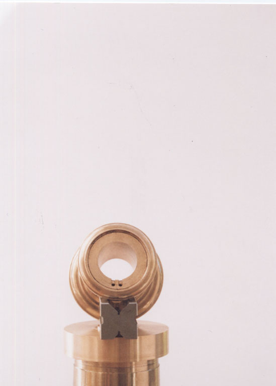
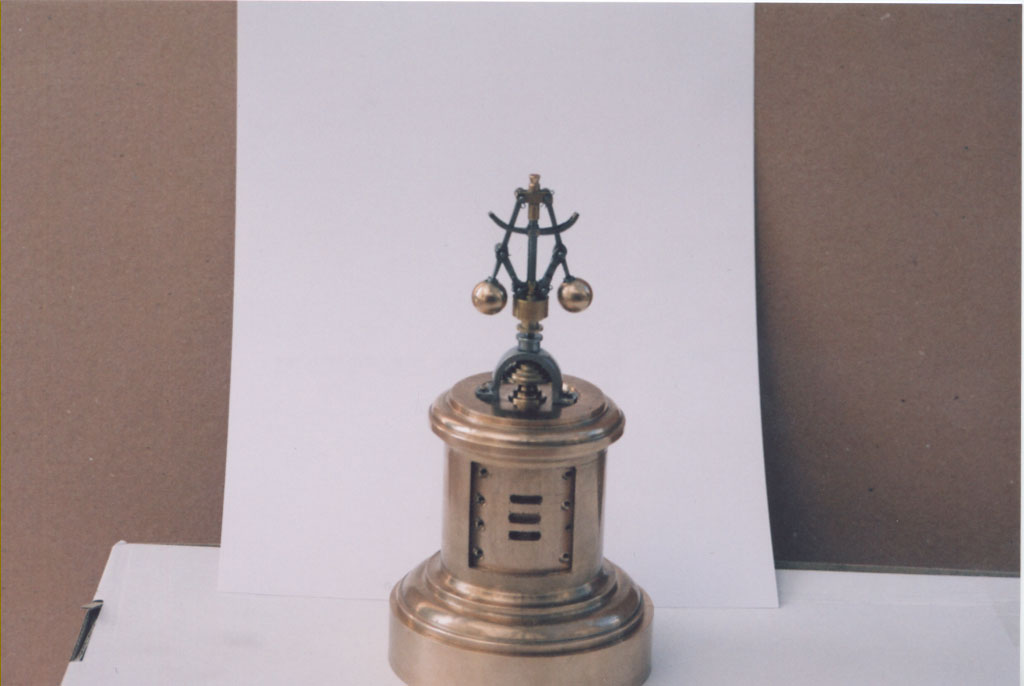
Cylinder in place - with top cover governor - piston |
 |
Cylinder in casing showing ports. |
 |
Steam chest tried for fit. |
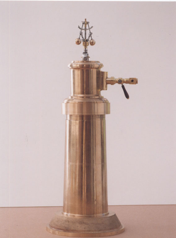 |
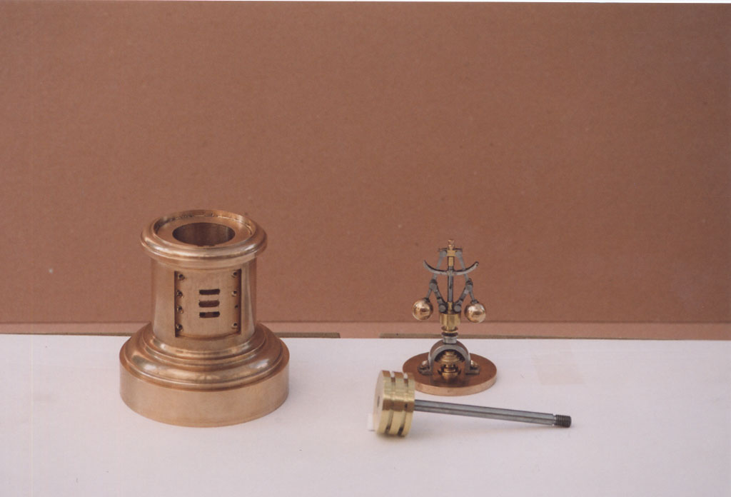
Mid build assembly to check that we'd got the scale and relative dimensions right. (Somebody said it looked like a fire extinguisher) |
 |
|
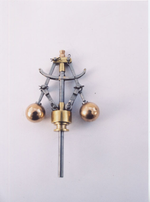 |
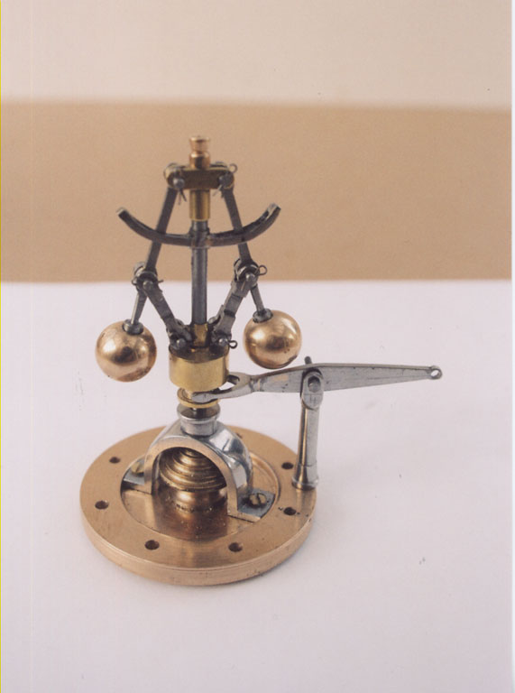
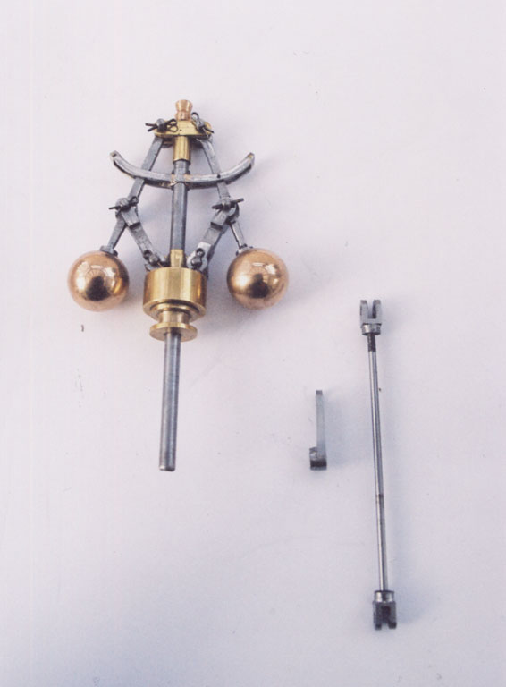
Governor (minus pulley block). Note 1/32" split pins in No. 68 drill holes crossdrilled in pins .2mm |
 |
|
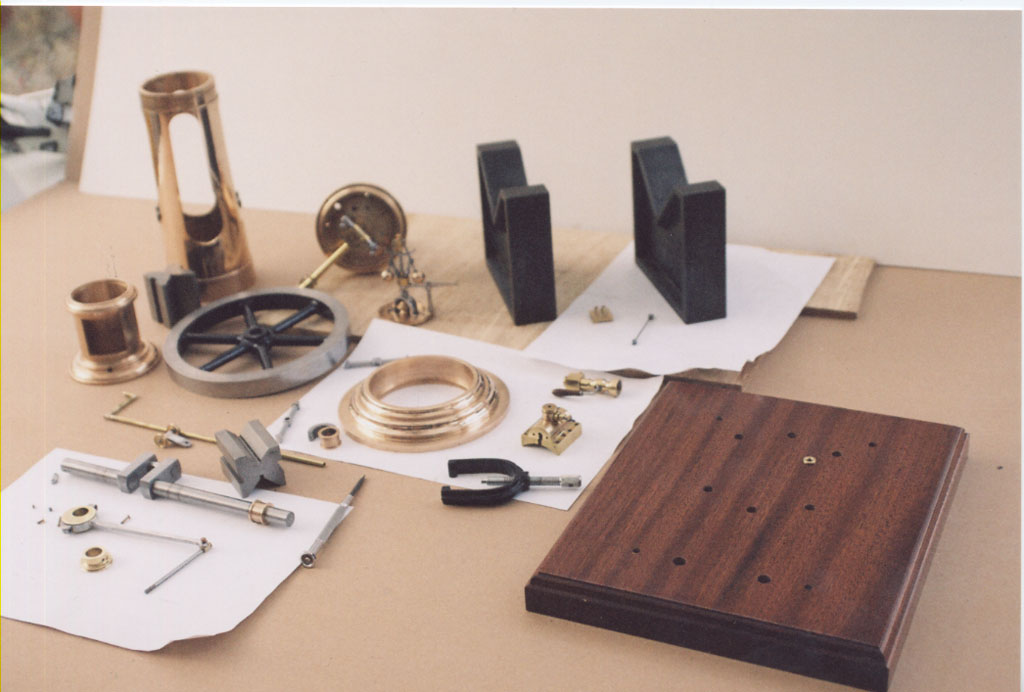 |
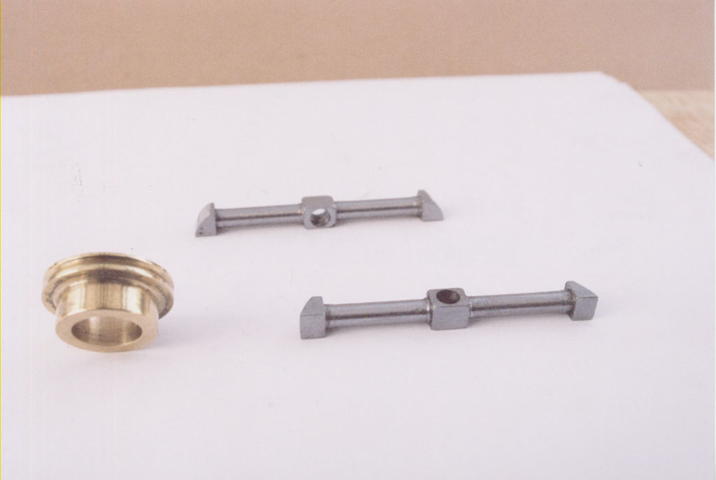
The bits (but not the vee blocks). |
 |
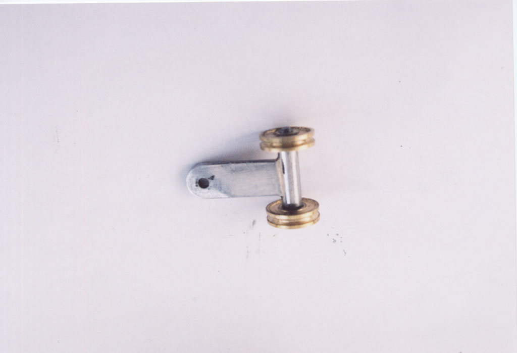
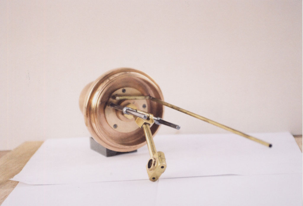
Eccentric strap + valve rod with reduced cross head. |
 |
|
 |
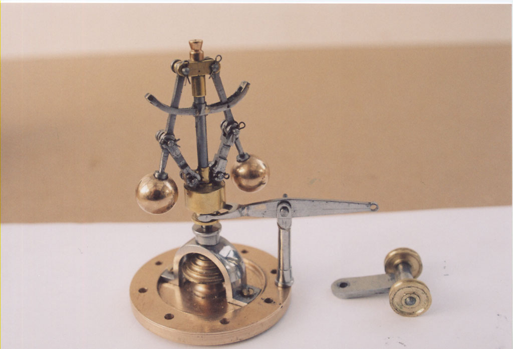
Governor gear pulleys. |
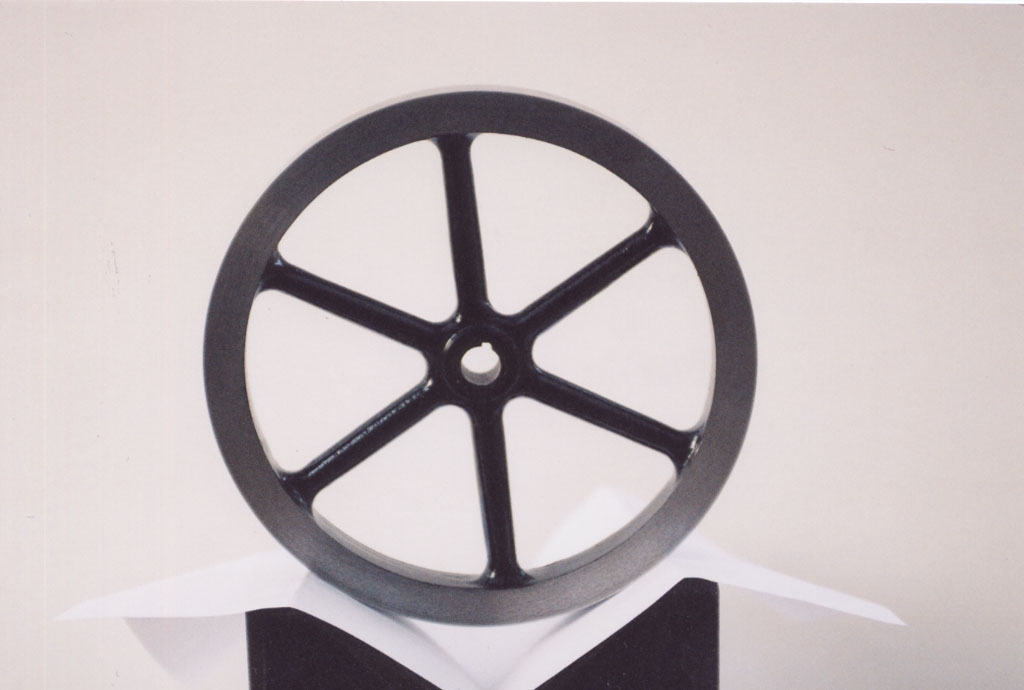 |
Flywheel secured to shaft with a 'saddle-key' ie. tapered and with a curved inner surface to match shaft. A very firm fixing. |
 |
Built up crank shaft. |
 |
|
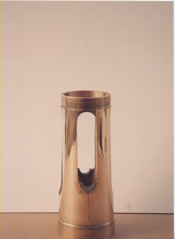 |
Showing long apertures cut. |
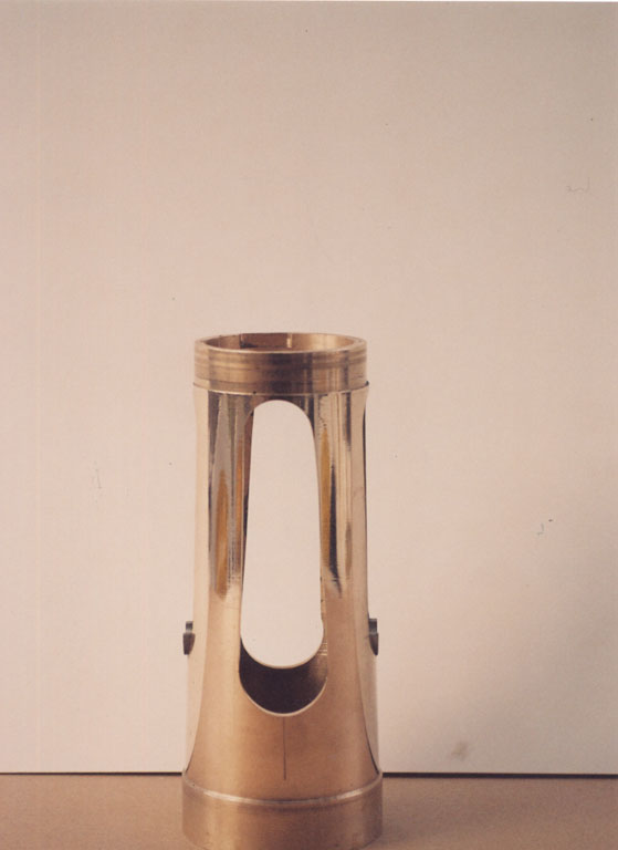 |
Showing short apertures and bearing halves in position. |
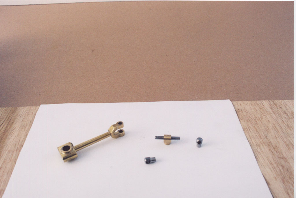 |
Con-rod big end and cross head components. |
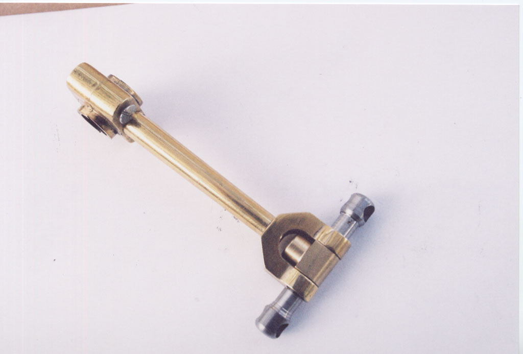 |
Cross head with extensions to fit guide bars. |
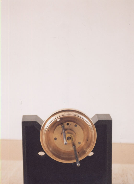 |
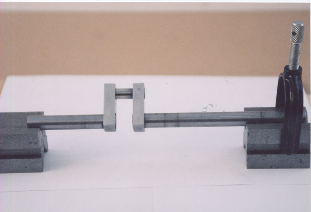
To position and fix guide bars was quite a problem. We couldn't see how the original ones were done but this is a very robust set up. |
 |
|
 |
Showing the guide bar horizontal supports. Again quite a problem solved by "file and error" (sorry). |
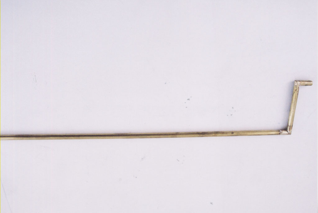 |
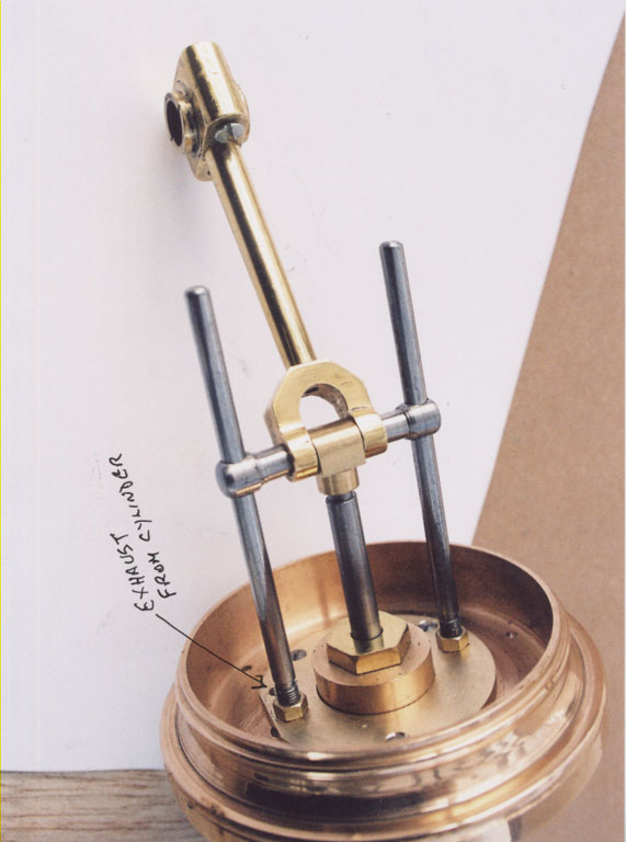
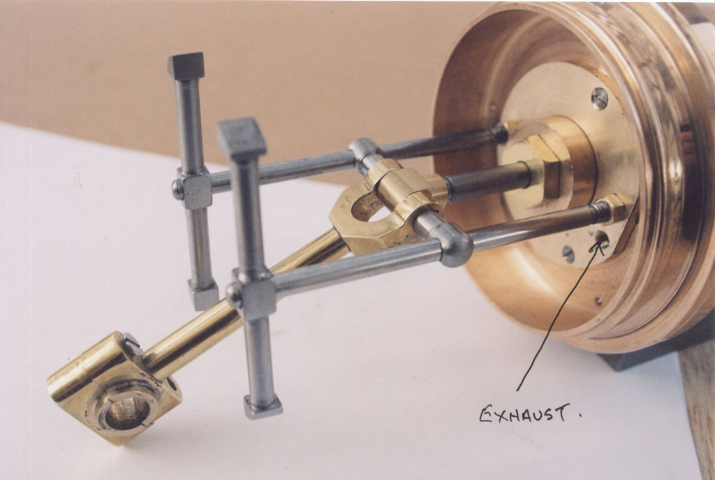
Exhaust pipe. This also was a problem but ended up quite simple. |
 |
There's only just enough room but it passes down the side of the column and into the base. |
 |
|
 |
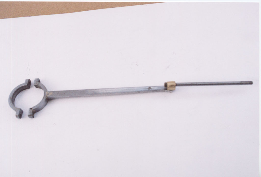
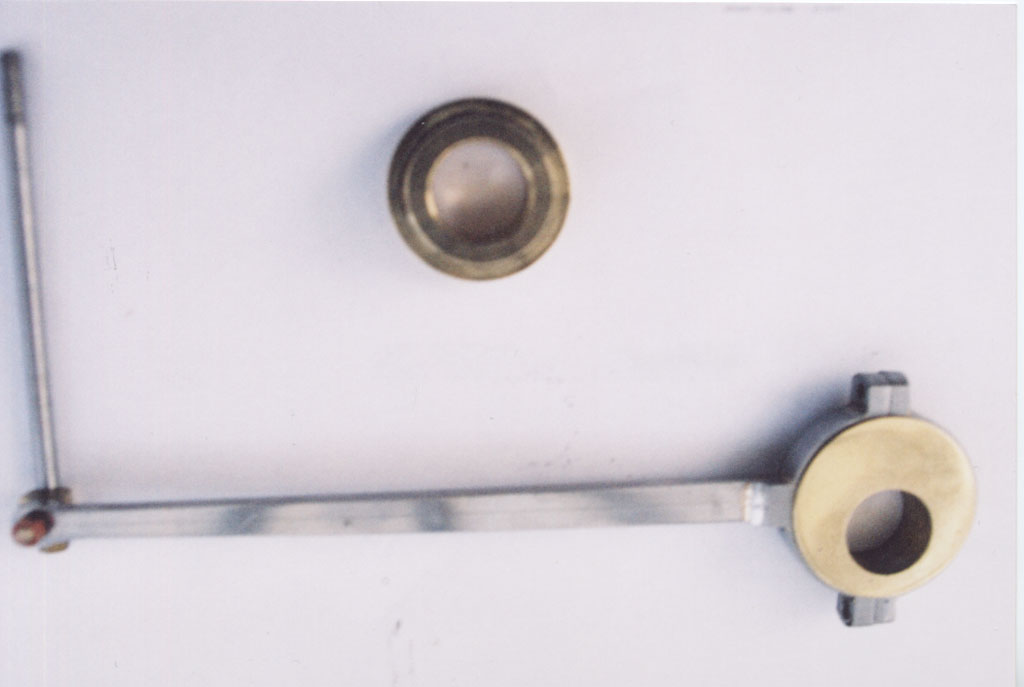
Governor and linkage components. |
 |
|
 |
|
 |
Steam chest curved to fit cylinder as is the side valve (2" 1.D) |
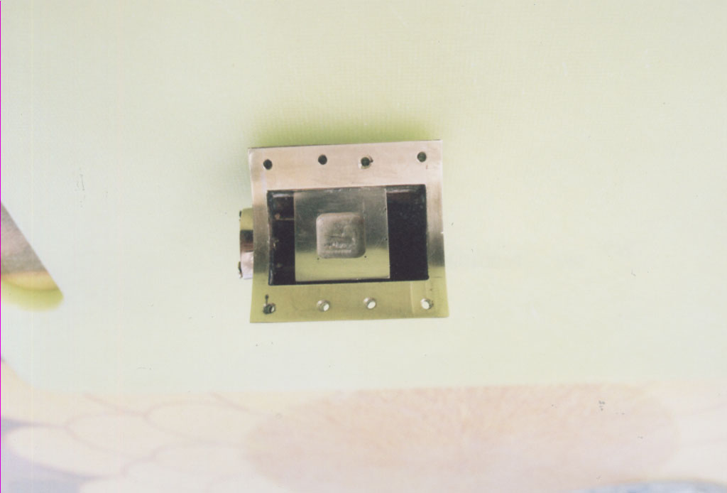 |
Inside of steam chest with valve insitu. |
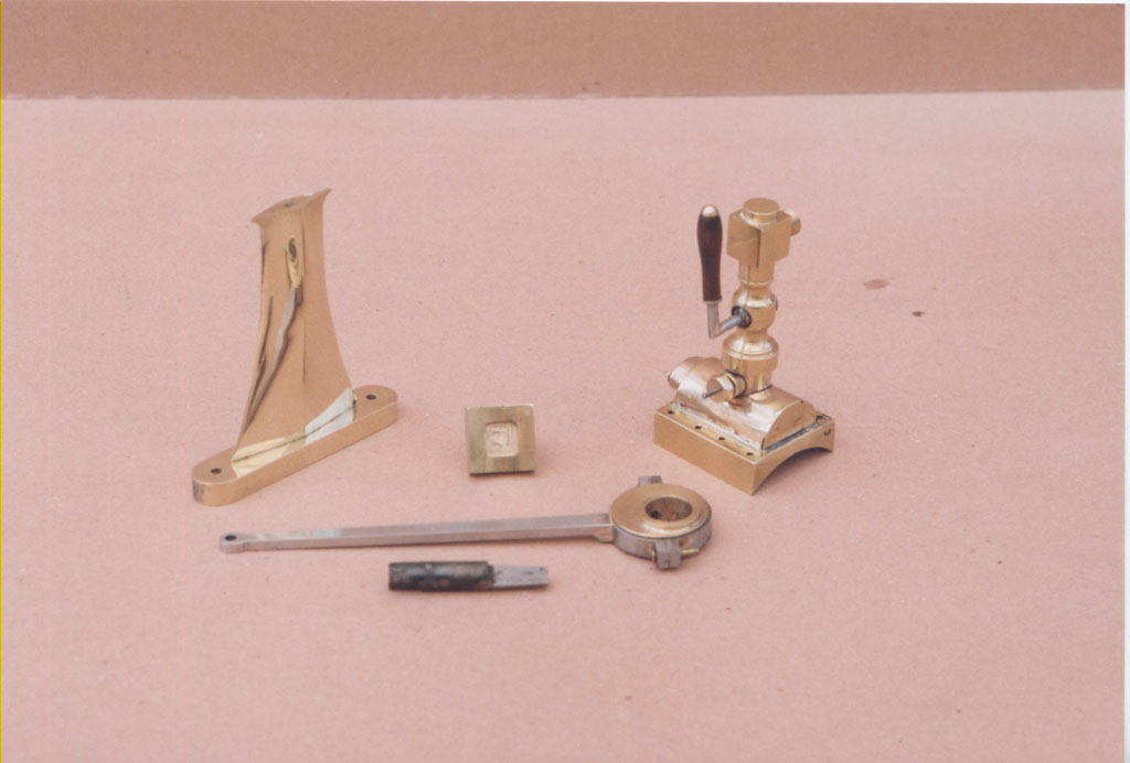 |
Outrigger bearing pedestal steam inlet valve and tapered reamer made for the steam valve. |